Monday, November 23, 2015

Faux Photometric Stereo Part III: Bare Minimum Material Building with Unreal Engine 4

     Hello Everyone! Sorry for the delay. This section should be pretty short and fairly easy if you have any knowledge of Unreal Engine. Unreal Engine 4 (UE4) is being used to make/render the material for a few reasons: A) It is free.* (*for development) B) It is an incredibly powerful real-time engine that is very deep and feature rich, and mostly user friendly. C) A massive, highly talented community that is willing to help if you get stuck.

     If you do not have any experience in UE4, please go watch the very informative series provided by Epic Games on their Youtube channel. Most of these videos were made before version 4.7 and they maybe inconsistent with how things are done now. Don't get frustrated if something isn't working, Check the Answers Hub first, for a solution. I will be using Version 4.10 for this quick demo.

Material Building in UE4


Bringing Everything Into the Engine

     Now that all the maps have been generated, launch UE4 and start a new project.  I generally start with the default map and Starter Content for testing materials.  I've set up my viewing area with a Material Preview Mesh which is available in the Starter Content folder (Content Browser Tab>Starter Content Folder>Props Folder>SM_MatPreviewMesh_02) and just copied and adjusted one of the floor static meshes to be a wall.

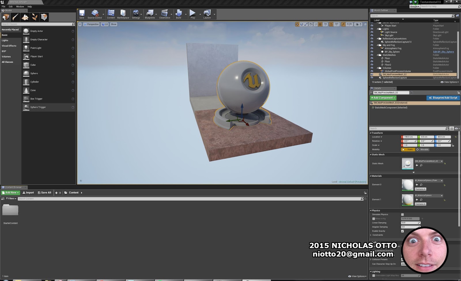
(Fig. 1) Start a basic environment to test materials

  1. In the Content Browser Tab, create a new folder and name it appropriately. I chose PAPERBAG.
  2. Create a new material in the folder by right clicking and selecting "Material".
  3. Select "Import" from the top of the Content Browser tab and navigate to the proper files to import them into the folder.
  4. Double click the material to open the  Material Editing tab, then tare the tab off into its own window (Left Click>Drag).
  5. Select all of the texture maps and drag them into the Material editing tab.


    (Fig. 2) Import texture maps then drag them into the Material Editing tab.
  6. Connect the textures to their proper node buttons on the Output Node.


  7. (Fig. 3) Textures connected to their proper node buttons on the Output Node.
  8. Done. Apply to any and all surfaces and stare in wonder.


  9. (Fig. 4) WHEEEEEEEEEEEEEEEEEEEEEEEEEEEEEEEEEEEEEEEEEEEEEEE.

     This is pretty much as basic as the process can get.  I do want to point out that there is a TON of work that can go into making this material look better during the Photoshop stages.  The first and most obvious would be making the texture map tileable. UE4 really likes maps that are a power of two, the engine will be able to ensure the texture looks good in many different situations. Another big improvement would be adjusting the images used to create the normal maps. It is a relatively small detail that the average person may not be able to pick out but most video game artists will view it as a huge glaring error. Take a look at the specular and normal map, then the rendered material to see if you can spot the problem:


The paper bag used for the capture was uniformly flat where the ink touches the paper. But because there was such a high contrast between the black ink and the light brown paper, the ink in the rendered material looks embossed which has lead to exaggerated highlights on the ink and the surrounding edges.
   
     It is very important to remember: the more care used during the Photoshop phase of this process, the better the end result will be. Again, this is by no means a "cheat" to make PRB materials without having to use a Photometric stereo capture system.  Photometric Stereo, depending on the amount of lights and the quality of the equipment used, will always be able to produce better quality maps, quicker. But this is another way to produce some materials inside of a real-time engine while having a lot of control over tweaking the texture during the processing stages.  I have been messing around with different filter stacks in Photoshop to produce better results and will probably share this information at sometime in the future.

Some things to remember whenever texture maps are being generated by hand:


  • Make them a power of two (2x2, 4x4, 8x8,, 16x16, etc).
  • Make them tileable.
  • Remove gradient lighting to improve repeatability.
  • Even out contrast/brightness on flat surfaces when generating normal and specular maps.
     Thank you for taking the time to read this and if you enjoyed reading the process please let me know!

Saturday, October 24, 2015

Faux Photometric Stereo Part I: Intro and Capture system

    Intro

     I have resurrected this old blog so that I may quickly share a process I have cobbled together for making texture maps that produce results that kind-of-but-not-really look like photometric stereo.  This capture and processing method should help with creating more realistic looking material shaders for real-time engines. What this process can do : Capture quality images and provide a solid base to create material shaders. What is cannot do: 100% faithful recreation of the material captured.  Artistic input is still needed to create a material that looks convincing.  Overly shiny/mirrored/clear coat/high gloss materials will require extensive work to look proper in a real-time engine.  Below is a an example of the end result inside of Unreal Engine 4.


     I will have a more in depth guide going over the development of an automated system at a later date. The paper bag texture used for the this guide was captured using a non-automated process, this means that it will be very easy for anyone on a budget to reproduce similar results, but your results may vary.

     I would love to say that the development of this process was all me, but I can't in good faith take credit for other people's hard work when I was smashing their processes together like a child attempting to hammer a square peg through a round hole. So I would like to give credit where credit is due:

Normal Map Photography - Ryan Clark - A great guide to manual normal map generation using light direction.

How To Split Specular And Diffuse In Real Images - John Hable - This guide is more about solving a specular map programmatically, but I am still wobbly when it comes to writing code. This guide inspired me to figure out how to achieve similar results with Photoshop filters.

Paul Debevec and his team at USC ICT Graphics Lab - If you don't know who ICT is, get acquainted.  These people are breaking the uncanny valley. 

Christopher Ellis - You tried your best to instill in me the power of tinkering during our time together at ATVI, but it didn't take hold until long after we parted ways. Thank you.

Now on to the guide!

Supplies used for Capture System

     I used some items that people on a budget may not be able to acquire, I just happen to be lucky enough to work at a place that has these materials just lying around. Below is what I used, but like everything in life, there are many ways to complete a task.

Capturing Needs:

  • DSLR - Anything will work. Better results can be achieved with better equipment.
  • Remote Shutter Release.
  • Framing/tripod - A pile of Alufix was just sitting around the studio.  I used this to create an obstruction free stand for the camera. More on this later.
  • Cutting mat with measurements.
  • Color chart.
  • Circular or Linear Polarizing Filter for Camera.
  • Light Source, preferably one that produces a sharp shadow.
  • Linear Polarizing film for light source(s).
  • Tripod or stand for light.

Setting up Capture System

(Fig.1) The Capture Setup. Blue = Framing. Orange = Camera. 
Yellow = Lights and their positions. Green = Cutting mat with measurements.
Light Blue = Capture Subject. Purple = Color Chart.

Camera Mount

     Unfortunately I never took images of the Alufix fixture made to support the camera, and I have already broken it down and moved onto a more compact design.  The framing was set up in a "T" shape, then legs were mounted to the sides to raise it off the ground to approximately 1 meter.  How high to raise the camera is dictated by how large the item being captured is and the focal distance of the camera lens (calculate depth of field).

Camera Setup

     The lens needs to be equipped with a polarizing filter and the camera should be in manual mode.  Manual mode allows for fine tuning of the images and insures that the lighting is more uniform from image to image. Pay attention to the type of polarizing filter used as it can mess with the camera's sensors.  The light meter is particularly sensitive to linear polarizing filters and will give false readings. If the lens is a variable zoom lens, find the focal length that works for the subject, then tape that ring down so it cannot move. For this process to work all images need to be taken with the same focal length and distance. A remote shutter release will also help prevent the camera from moving around during the capture. Also shooting in a RAW format is recommended as further tweaking can be done after the capture session.

Light Setup

     I built a light from a led strip, and scrap ply board.  It gave off a good amount of light and was extremely cheap to make. I have moved away from using this light because it produces soft shadows and the best light for this system is a spotlight. The sharper the shadows, the more accurate the normal map.
(Fig. 2) LED strip light.

(Fig. 3) LED strip light with polarizing film.

Color Chart

     A color chart will help correct the color of the raw images after the capture.  If only one light source is being used then the chart only needs to be in one photo. If multiple light sources are being used, the chart needs to be in every shot as lights can vary in color and brightness (especially cheaper LEDS).


Capturing the Images

Brief Overview 

     It is necessary to take eight images for this process, four images that lack specular information and four which contain specular information. It is possible that more images of the subject lit from different directions and angles would help create a more complete map, but I haven't gone that far in my testing.  The four non-specular images will help us create our color and normal maps. The four specular images plus the color map will help create a good base for the specular map.  The specular map could also be used as a roughness map (covered in Part II). 

The Capture Process

     The light(s) should be set up equidistant from the subject and arranged left, right, top, and bottom. (Please refer to Fig. 1). The reason for these particular light positions goes back to Ryan Clark's article.  For the paper bag photo set, the light was attached to a tripod.  Since I was using a single light, I would capture an image and then move the light.  A major problem of moving a light by hand is that it is hard to keep the same distance away from the subject in every image. Varying light intensity will effect the end results.

What I captured:

Polarized


Non-Polarized


Thanks for reading! Part II will cover processing the images, and should be released eventually.


Faux Photometric Stereo Part II Processing the Captured Images.

Processing the Raw Images

      I'm going to switch over to bullet points to make this part of the process easier to follow. This process can be done in Photoshop or GIMP (I use GIMP for the manual normal map generation only because I haven't used PS in so long that certain procedures don't work like they used to back in the CS2 days).
(Fig. 4 RAW image import and correction)
  1. Bulk import the RAW images into Photoshop for a couple of corrections (Fig 4). 
  2. Select the "White Balance dropper" from the upper tool bar and click a medium gray color.  Adjust exposure if necessary 
  3. Select the Lens correction tab (under the histogram, sixth from the left) and check "Enable Lens Profile Corrections".  If the lens used was a standard one, then all adjustments will be done automagically. This is an important step for a texture map that has features which run to the edge of the map. Lens correction will remove barrel distortion, which makes straight lines have a curve to them due to the multiple glass/plastic lenses that make up the final lens.
  4. If the subject was shot with a single light it is OK to synchronize all the RAW images and Save.
  5. If the subject was shot with different lights, it is probably better to adjust per RAW image.
  6. Copy all the images onto one canvas.
  7. Rotate Canvas, if  needed.
  8. Check images for alignment issues. If there aren't any alignment issues skip to step 8.
    • Hide all layers but one, then set that layer to 50% opacity and move it to the top of the stack. This is the alignment layer.
    • Unhide one of the hidden layers below the alignment layer and set it as the active layer. 
    • Look for misalignments, they will be pretty obvious.
    • Using the grid on the cutting mat, or text on the subject/color chart, Move the active later around using the arrow keys to push it into alignment.
    • If it becomes hard to tell if the layer is really in alignment with the top layer, turn the Alignment layer to 100% opacity and flick the viability off and on.
    • Do this for all layers.
    • Crop Canvas to what will eventually become the texture.

      (Fig. 5) Check alignment from image to image

Creating the Color map

  1. Place all non-specular images in a folder and place all specular images into a separate folder then hide that folder.
  2. Rename files to correlate with the light direction (Top, Bottom, Left, Right).
  3. Select all layers in the non-specular folder and set the layer style to "Lighten". (Fig. 6)  This filter only allows the lighter parts of the layer to transfer down, making it a powerful tool to eliminate most of the shadows from the final image.
  4. Duplicate all the layers and merge the duplicates into a single layer and rename it to "Color".
  5. Duplicate the "Color" layer and Desaturate (Image>Adjustments>Desaturate)
  6. Invert the colors of the duplicate (Image>Adjustments>Invert), then set the layer style to "Overlay". This step ensures nearly all the light information from our color map has been removed.
  7. Save out TARGA file as Paperbag_color. (You may have to change the Image mode to 8bit, Image>Mode>8bit).
    • This will create a very simple color map that will have some problems.  I am currently messing around with generating a more accurate map.
(Fig. 6) Color Map Creation.


Creating the Specular Map

  1. Hide the Color Folder and unhide the Specular Folder.
  2. Rename files in the Specular folder to correlate with the light direction.
  3. Select all layers in the non-specular folder and set the layer style to "Lighten".
  4. Duplicate all the layers and merge the duplicates into a single layer and rename it to "Spec".
  5. Desaturate the created layer and save out Spec map.
    • This will create a very simple specular map that will have some problems.  I am currently messing around with generating a more accurate map.


(Fig. 7) Specular Map Creation.


Creating the Normal Map

     I will be following Ryan Clark's  Normal Map Photography article and switching over to GIMP to complete the Normal Map generation.

Photoshop Prep:
  1. Right Click on a layer under the "Color" folder and select "Duplicate Layer". (Fig. 8)
  2. In the popup menu under "Document:" select "New" in the drop down menu.
  3. Name the file something that will be easy to sort such as "NORM_RIGHT" so that you know that this file is lit from the right and for the normal map process.
  4. In the new window desaturate the layer and save out as a TARGA file.
  5. Repeat steps 1-4 for the other 3 files.
(Fig. 8) Prepping the Normal Map Files.
GIMP:
  1. In Gimp select File>Open As Layers and select the Top and Left lit images. (Fig. 9)
  2. Change the image mode to "Grayscale" Image>Mode>Grayscale.
  3. Select Color>Components>Compose. This is where to define which layer will represent a color channel.
    • The Left lit image will be the Red Channel.
    • The Top lit image will be the Green Channel.
    • The Blue channel will be set to "Mask" with a value of "0".
    • Click "OK" and a new window will open with the layers as color channels.
  4. Select Color>Levels.
    • The Output Levels should be set to "127" on the black side, and "0" on the white side.
    • Click "OK".

      (Fig. 9) Creating the first part of the Normal Map.
  5. In Gimp select File>Open As Layers and select the Bottom and Right lit images. (Fig. 10)
  6. Change the image mode to "Grayscale" Image>Mode>Grayscale.
  7. Select Color>Components>Compose. This is where to define which layer will represent a color channel.
    • The Right lit image will be the Red Channel.
    • The Bottom lit image will be the Green Channel.
    • The Blue channel will be set to "Mask" with a value of "0".
    • Click "OK" and a new window will open with the layers as color channels.
  8. Select Color>Levels.
    • The Output Levels should be set to "128" on the black side, and "255" on the white side.
    • Click "OK".
    (Fig. 10) Creating the second part of the Normal Map.
  9. Copy the "Bottom+Right" result to a new layer in the "Top+Left". (Fig. 11)
  10. With the "Bottom+Right" at the top of the layer stack, set the layer style to "Overlay".
  11. Select Layer>New from Visible and hide the other layers.
  12. Go to the Channels tab and hide the Red And Green Channels.
  13. Also, make sure only the Blue Channel can be edited by clicking on the Red and Green Channels (if the channel is highlighted in blue then it cant be edited by clicking on them).
  14. Fill the layer with White.
    • White was already my foreground color so I just clicked Edit> Fill with Foreground Color.
  15. Unhide the red and Green Channels.
  16. Save the image, as it is now a complete normal map.
(Fig. 11) Finishing the Normal Map.

I will end Part II here as all the maps have been completed.  This is by no means the end of the amount of work that could be done to the images to improve how they will look in a real time engine, but those techniques are outside the scope of  this write up.  In the next section you will notice what could have been done to ensure the material looked beter, but hopefully these artifacts will give everyone a good idea of how to be more successful in their own adventures. See you soon!


Wednesday, June 20, 2007

Not Dead, Just Busy

We finally have work to do again, so all my other stuff is being pushed off. Back soon.

Friday, June 15, 2007

Two-Face Round 3


didn't get much accomplished today, but its getting there.

Thursday, June 14, 2007

Two Face Round 2

didn't have work from anyone so i messed around more on Two Face

2-Face


So I figured I'd push the proportions on my face and setteled on making Two-Face from the Batman Series.